The Silicon Labs Busy Bee 3 (EFM8BB3) MCU has multiple timers and oscillators available, and this EFM8 timer tutorial shows you how to use one to blink an LED. The LED’s only purpose is to be a quick and easy way to test your code.
A timer is a feature offered by microcontrollers that enables you to execute code every time it ‘ticks’ (overflows). The term normally used for that is ‘overflows’, I said ‘ticks’ to clarify that it does something after a specified time period elapses.

For example: You can make a timer overflow every 5 seconds, and have it execute code that turns on/off an LED (or does any other task you wish). You can configure it to continuously start over and keep executing that code every 5 seconds.
This is better than loops if you are doing something that requires a specific interval. However, If you’re looping through an array, a timer is not necessary (and is also a waste of time). This tutorial will show you how to blink an LED.
EFM8 GPIO: This is what you’re using to blink the LED
As explained in greater detail by my Universal Bee GPIO tutorial, GPIO is what you use to switch pins on your EFM8 microcontroller on or off. The Silicon Labs EFM8 Busy Bee 3 used in this tutorial is very similar, so that tutorial will be helpful if you’re not yet familiar with GPIO on the EFM8 series. This is essentially a GPIO guide, but with a timer in this case.
Your EFM8BB3 has GPIO functionality that enables you to write a ‘1‘ or ‘0‘ to a pin. A ‘1’ turns the pin on at 3.3 Volts, and a ‘0’ turns it off (0 Volts). The timer code we will implement is going to alternate between a 1 and a 0 to switch the GPIO pin that powers the LED on and off respectively.
Remember: The EFM8 GPIO pins are only for discrete electronics, so only use a discrete LED that consumes less than 20 mA at 3.3 Volts. Page 38 of the EFM8BB3 datasheet says that the absolute maximum current that can be sourced or sunk by any of the I/O pins on that model is 100 mA, so you should stay well under that.
Before we continue, take a look at the EFM8BB3 itself. If you’re using it with the SLSTK2022a starter kit, what it does is help you to debug and connect things to it more easily, as the EFM8BB3 is a very tiny microcontroller!

Once we’re done with this tutorial, this same code can be used with a relay module to switch an indicator (blinker), fan, heater, or anything else on at any interval you wish.
The EFM8BB3 is equipped with/supports the following oscillators that can be used to drive timers:
- HFOSC0 (the one we’re using for this project).
- HFOSC1.
- LFOSC0.
- EXTOSC (optional, external oscillator you can connect to the EFM8BB3).
The EFM8BB3 is equipped with the following timers (read more about each timer’s features on page 11 of the EFM8BB3 datasheet):
- Timer 0.
- Timer 1.
- Timer 2 (the one we’re using for this project).
- Timer 3.
- Timer 4.
- Timer 5.
First step: Create a new MCU project in Simplicity Studio
Download Simplicity Studio 4, and then select the new MCU project option from the ‘File’ menu. Ensure that the correct microcontroller/development kit is selected: ‘EFM8BB3 Busy Bee Starter Kit Board’. Click ‘Next’. It should select the 8051 SDK automatically in the ‘SDK’ field, as this is one of the 8051-based microcontrollers.
When prompted, select the ‘Simplicity Configurator Program’ option, as we will be using the configurator to configure our timer to reduce the amount of coding we have to do. Click ‘Next’ and select the device ‘EFM8BB31F64G-B-QFN32’ or whichever EFM8 Busy Bee 3 variant you’re using. Name the project ‘Timer Example’ (after all, it is a timer example!). Click ‘Next’ again and then ‘Finish’.
Second Step: Enable Interrupts And The EFM8 Timer In The Configurator
If Simplicity Studio didn’t already load the configurator with a diagram of the EFM8BB3 pinout, open the configurator file called ‘TimerExample.hwconf’. Of the three tabs at the bottom, select ‘DefaultMode Peripherals’. You will now see the EFM8 Busy Bee’s peripherals and their configuration, all at your fingertips!
Check the boxes ‘Clock Control’, ‘Interrupts’, ‘Timers’, and ‘Watchdog Timer’. Select ‘Watchdog Timer’ and set the ‘WDT Enable’ on the right side of the screen to ‘Disabled’ so it doesn’t automatically reset your MCU while you’re using it (the Watchdog Timer does serve a good purpose, though! It just isn’t needed for this example).
Now select ‘Clock Control’ and set ‘Clock Source Divider’ on the right side of the screen to ‘SYSCLK / 1’. ‘Select Clock Source’ should be set to ‘Internal High Frequency Oscillator 0’. Now you can select ‘Timers’.
You should see tabs for all the timers to your right as shown below.
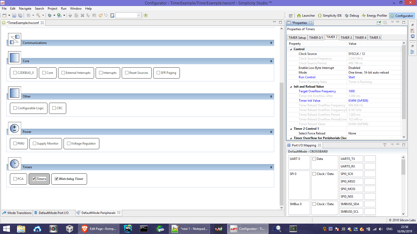
Select the ‘Timer 2’ tab, since that’s the timer we’ll be using. Set the ‘Run Control’ field to ‘Start‘. This turns on the timer. Set the ‘Target Overflow Frequency’ to ‘1000‘ and the ‘Timer Init Value’ to ‘63494‘ as highlighted in the screenshot above. The goal of that was to make the timer ‘overflow’ or ‘tick’ as I like to say after 1 millisecond. The ‘Timer Running State’ should now say ‘Timer is running’.
Third Step: Configure The EFM8 GPIO Pins
The EFM8 uses a Crossbar to manage GPIO pins in the configurator. Go to the ‘DefaultMode Port I/O’ tab in the bottom centre of the screen and click ’20/P1.5′ on the MCU pinout image. That is Pin 1.5, which is the pin the blue LED is connected to. That is what we will switch on and off (blink) with our timer.
Set the ‘Skip’ option to ‘Skipped‘ and the ‘IOMode’ option to ‘Digital Push-Pull Output‘.
Enable EFM8 Interrupts And Start Coding!
Go back to the ‘DefaultMode Peripherals’ screen where you enabled Timers, Interrupts, and click ‘Interrupts’. Set ‘Generate Interrupt Functions’ to ‘Enabled‘, and then set ‘Enable Timer 2 Interrupt’ to ‘Enabled‘. The IDE should have now generated a file for you named ‘Interrupts.c‘ (this occurs after you enable interrupts). That contains the Interrupt Service Routine (ISR) that will be executed whenever the timer ticks. Therefore that code will be executed every millisecond.
Before you go there, go to the ‘TimerExample_Main.c’ file under /src and enter the following code inside the ‘main’ function (inside the brackets immediately after ‘void main()’) to enable all interrupts, and enable Crossbar.
IE_EA = 1; XBR2 |= 0x40; //Enable Crossbar so we can easily turn pins on and off.
Now go to the ‘Interrupts.c’ file under /src and write the following code under the last ‘#include’ line. The ‘SI_SBIT’ line defines pin 1.5 as ‘LED1’ to make your code more readable and easy to work with. The line after it declares and initializes the counter variable we will use to count up to 1000 milliseconds.
SI_SBIT(LED1, SFR_P1, 5);
int counter = 0;The EFM8BB3 Timer Code Sample
Write this in the Timer 2 interrupt service routine:
TMR2CN0_TF2H = 0; //Clear the interrupt flag for Timer 2.
counter = counter + 1; //Increment by one every ms.
if (counter == 1000) { //If counter = 1000 ms or 1 sec, then:
LED1 = !LED1; //Blink the LED.
counter = 0; //Reset the counter.
}Why did I set it to tick every 1 ms if I really wanted the LED to blink every 1 second?
I’m not trying to be annoying! You’re going to need timers for much more than just blinking LEDs. Sometimes (often), you’ll find yourself limited to only one oscillator for some reason, but you have multiple peripherals or tasks running that require that same timer to operate at a certain speed (for example, the UART requires it to operate at a certain frequency).
In such a situation, you can make a simple counter like that to make other tasks execute at a different interval than the UART or any other peripheral does, and without interfering with your clock or timer settings!
I actually did do this in one of my projects, which uses an UART that I didn’t want to slow down to achieve the desired interval. This will also come in handy if you’re also using the analog-to-digital converter (ADC).