By Nicholas Brown.
If you purchased a Texas Instruments Launchpad TMS57004 (or other TMS570 series) MCU and don’t know where to begin, you’re not alone. I was recently in the same boat. This automotive microcontroller went from intimidating me with its seemingly complex interface, to amazing me with its simplicity.
While the TMS570 MCU family isn’t intended for beginners, you can still get started fairly quickly using this tutorial, and learn a little about embedded systems development. The TMS570 series is a family of automotive MCUs for embedded safety-critical applications. These MCUs are used to do things such as control your anti-locking braking system, power steering system, HEV and electric vehicle inverters, among other things.
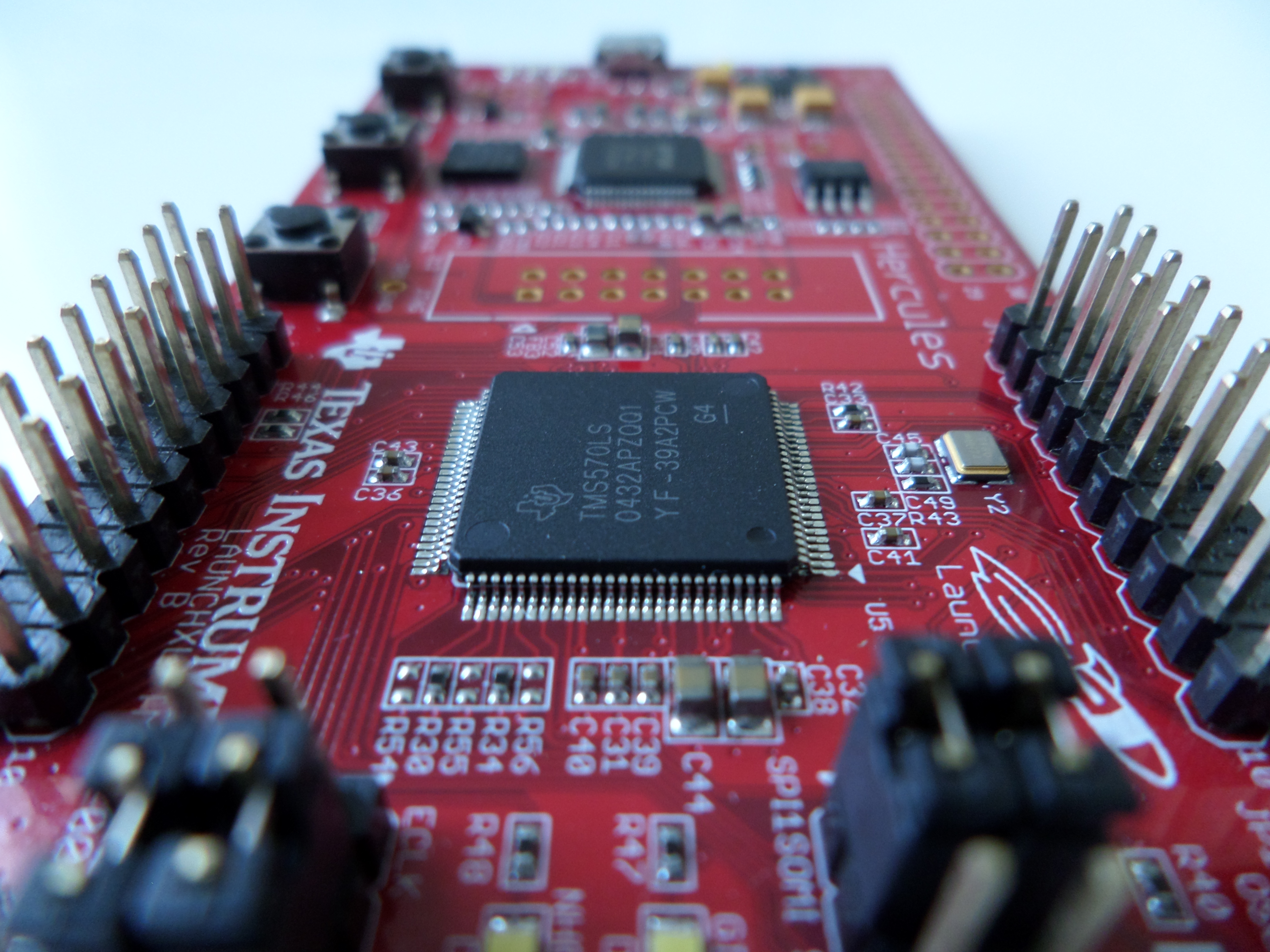 Texas Instruments Launchpad TMS57004 MCU evaluation kit (consisting of the TMS570LS04x MCU).
Texas Instrument’s official tutorial is called Project 0, which can be done very quickly and easily, but this tutorial will take you a step further and get the process of identifying key functions you’ll use most often out of the way. Project 0 introduces HALCoGen, which is a HAL code generator. HALCoGen enables you to create a PWM signal using the HET by typing only three lines of C code (and a few clicks).
If you’re using CCS, you would enter the following code.
#include "het.h" hetInit(); while(1);
This is awfully simple, and an easy way to try out your new Launchpad, but you will want to programmatically control your PWM signal using algorithms/conditional statements. This can be done using pwmStart(), pwmStop(), pwmSetDuty(), among other functions. This tutorial will introduce you to those functions so you can turn your PWM signal on or off with only one line of code.
- HALCoGen Setup.
- Set Up CCS.
- Start Coding.
- Adjusting The Brightness Of The LED With The ‘pwmSetDuty’ Function
If you’re accustomed to the MSP430, you were probably using GPIO (often called GIO) pins instead. The Hercules TMS570LS04x (which is the model we’re using for this tutorial) has both HET (N2HET in the case of this model) and GIO pins. The N2HET pins offered by the TMS570 enable you to generate a PWM signal right out of the box. This enables you to spend less time learning how PWM works, and more time completing your project.
If you want to read a more comprehensive article explaining how PWM works, I wrote on here.
HALCoGen Setup
Before we get started, create a HALCoGen project (you can get HALCoGen from Texas Instruments’ website) and configure your PWM and HET settings. HET stands for ‘high-end timer’.
Go to File > New > Project > Select the device ‘TMS570LS04x‘ > Then select the first option to the right which is ‘TMS570LS04x‘. Name the project MyProject and store it in any directory you’d like to, but note the path in the Location field.
Afterwards, click the TMS570LS0432PZ tab, navigate to the Driver Enable subtab, and then tick the checkbox labelled ‘Enable HET drivers‘.
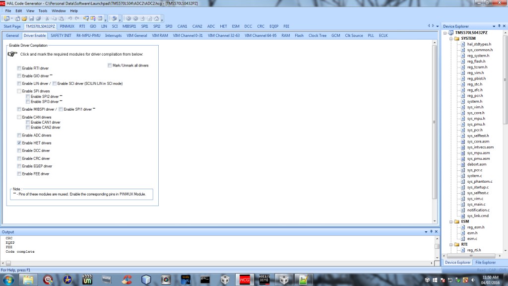 Enable the HET drivers so HALCoGen can generate the necessary files (this includes het.c).
Next, go to the HET tab and click the Pwm 0-7 subtab. You can use whichever you like, but for this example I used PWM 0. Enable PWM 0 as I did in the screenshot below, and select pin 8. This just means it will supply the PWM signal to pin 8. I chose that pin because one of the TMS570’s built-in LEDs is connected to it. The LED marked NHET08 will switch on when we’re done here.
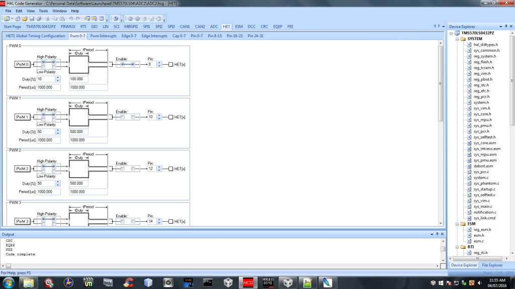 In this screenshot, you can see the PWM timer settings.
You may have noticed the ‘duty cycle’ setting. That’s the fraction of the time that the pin will be on. Mine is set to 10%, but you’re welcome to increase that to whichever value you wish (up to 100%). Now set the Period [us] field to 1000000 (this field accepts microseconds).
Finally, you can wrap up the HALCoGen configuration process by going to the Pin 8-15 tab and setting pin 8 to the output direction by ticking the first checkbox (from the left) as shown below. You also need to set the output value of pin 8 to 0 via the DOUT checkbox. Bit 8 is pin 8 (referred to as NHET08 on the TMS570LS04x). An output value of ‘0’ is equivalent to ‘OFF’. We don’t need this on since we’ll be switching it on ourselves using the pwmStart() function.
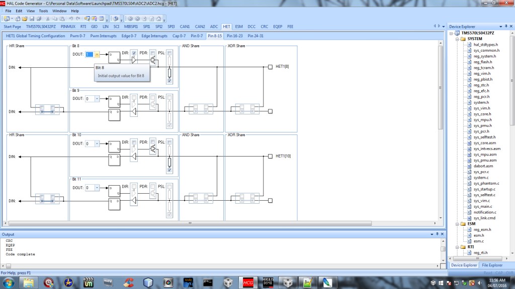 HET pin configuration.
Click File > Generate Code, or press F5.
Setup CCS
The next step is to launch Code Composer Studio. If you don’t already have it, you’ll need to log in with your TI account and download it from them. CCS is available for Linux, but HALCoGen is not as yet, so you need a Windows PC for this.
In the workspace field, enter the exact same directory that your HALCoGen project folder is in. If your HALCoGen Location field was set to ‘C:\Launchpad’ and your project name was Blink, then your HALCoGen folder was placed inside ‘C:\Launchpad’, which will be your workspace. Your CCS project directory should also have the same name as your HALCoGen project directory. Your CCS and HALCoGen files should be in the same directory.
So your HALCoGen project directory should be C:\Launchpad\MyProject, and your CCS project directory should be C:\Launchpad\MyProject. The next step is to include the include directory generated by HALCoGen in your project. Go to File > Properties > Include Options, and click the icon with the green plus sign on a file. Click Browse and select the include directory, which is found in the MyProject folder.
You can now start coding!
Start Coding
Open sys_main.c and add the following code between the /* USER CODE BEGIN (1) */ and
/* USER CODE END */ comments to include the required header file for the HET timer.
#include "het.h"
Next, enter the following code after /* USER CODE BEGIN (3) */, because that’s where the main function is.
hetInit(); pwmStart(hetRAM1, pwm0);
Voila! You can now load your program onto your TMS570 (this code was tested on the TMS570LS0432PZ, but can work on other Hercules models with little or no modification). Build it (by clicking the hammer icon), and run it (by clicking the green bug icon, which uploads your code to the TMS570). You should see the NHET08 LED blinking every second. Notice pwm0? That is the same PWM signal we selected (PWM 0) in HALCoGen earlier. From there, it’s straightforward.
- pwm0 is PWM 0.
- pwm1 is PWM 1.
- pwm2 is PWM 2.
- pwm3 is PWM 3.
- pwm4 is PWM 4.
- pwm5 is PWM 5.
- pwm6 is PWM 6.
- pwm7 is PWM 7.
The following lines of code set the PWM duty cycle and stop the PWM signal respectively (place them in the main function after hetInit()), as you did with the code above).
pwmSetDuty(hetRAM1, pwm0, 5U); pwmStop(hetRAM1, pwm0);
Adjusting The Brightness Of The HET LED With pwmSetDuty
The third parameter (5U) is the duty cycle of the PWM signal. ‘5U’ in this case is 5%. Increasing it will increase the brightness of the LED, and vice versa. If you would like to adjust the brightness of the LED, change the Period[us] field to 1000. This causes the LED to blink every 1000 microseconds (or 0.001 seconds), but it will appear to be ‘on’ all the time, so you won’t see it blinking. Now that you’ve done this, adjusting the duty cycle will increase/decrease the brightness of the LED (and the average voltage), in the following example, I increase the duty cycle by changing 5U to 50U (5% to 50%):
#include "het.h" #include "sys_common.h" void main(void) { hetInit(); pwmSetDuty(hetRAM1, pwm0, 50U); pwmStart(hetRAM1, pwm0); }
You can switch to another pin using HALCoGen (under the tab in which we set PWM 0 to pin 8 above) and generate the code again without losing what you have written in the editor, although I would advise you to make a copy of it, as I can’t guarantee that.
If you switch to another pin (you can find the pin numbers on the underside of the board), you can use the current from that pin to control a transistor, which in turn enables you to control a larger current. You could use it to control the speed of a fan, the brightness of a light bulb, among many other things. PWM is desirable and widely used because it is an energy-efficient way to control the speed of motors. Example applications include hybrid and electric vehicle motors, inverter air conditioners, inverter refrigerators, computer fans, among others.
You’re likely to have fun with microcontrollers like the TMS570. The possibilities they provide are endless! To get started, two helpful tools would be a multimeter and an oscilloscope to ensure voltages and currents are what they should be, and to view oscillating signals (for example: PWM signals and alternating current) respectively. A decent multimeter can be obtained for less than $50, but oscilloscopes are unfortunately very costly.
I would recommend that you purchase a multimeter first, and then give a budget oscilloscope like the 50 MHZ Rigol DS1054Z a try in the future. If you can afford it, there is also the 200 MHZ Keysight 2000X-Series. An oscilloscope is not absolutely necessary to get started, but will likely be useful if you’re building a pure sine wave inverter, for example. It will help you to ensure that your sine wave turned out exactly as it should to ensure optimal performance, and avoid damage to appliances.
Code tested with CCS version 6.1.1.00022.