The Arduino platform has blossomed into a large ecosystem of developers and products capable of using the same or similar syntax. Learning the Arduino syntax will enable you to use a broad variety of development kits on the market today. This tutorial covers the very first steps required to program your Arduino safely.
Table Of Contents
- Introduction to Arduino.
- What Are Pin Headers?
- Let’s Do Our First Arduino Code Sample.
- Dimming An LED: An Arduino PWM Code Example.
- Code Sample: Reading From Your Arduino’s GPIO Pins.
- Arduino Serial Communication: Using It To Observe The Outcome Of Your Programs.

A Brief Introduction To Arduino
An Arduino is a development platform used by many development kits that operate using Atmel-based microcontrollers. Arduino doesn’t refer to a particular microcontroller, but rather a platform for microcontrollers.
For example: The Arduino Uno used in this tutorial is a kit that has an Atmel ATmega 328P microcontroller (MCU). It is an 8-bit MCU with a 16MHZ RISC processor and 32KB of built-in flash memory.
The microcontroller itself (the ATmega 328P) is a tiny chip plugged into the Arduino board, and the Arduino board provides a beginner-friendly interface with a USB port, pin headers, DC power jack, among other things to help you program or connect things to it more easily. I encourage you to learn more about the ATmega 328P by reading its datasheet.
Pin Header
A pin header is an attachment with several pins on it that are larger and stronger than the pins found directly on a microcontroller. The pin header is attached to the Arduino kit’s board and provides an easy connection to a microcontroller’s tiny, fragile pins via easy-to-find pin plugs.
Pin Plugs: A pin plug, otherwise known as a jumper wire is a simple wire with a single plug on the end that you can use to connect external devices to your Arduino. Each pin plug can connect to one pin on your Arduino. For example, one wire could be connected to pin 13 (which will be used in this tutorial) and one other wire could be connected to the ground pin to power a tiny LED.
Why the emphasis on a tiny LED?
A microcontroller (and this one is no exception) is built to only supply very small amounts of current that are intended to serve as a signal, which triggers a larger switch. An example of a larger switch is a transistor.
Don’t draw more than 20 milliamps (mA) of current from your Arduino’s GPIO pins, otherwise you may damage it. Such a small current can easily switch on a transistor, and the transistor could in turn switch on a motor, relay (this is another switch controlled by a small current, except it is mechanical), a fan, a larger LED, among countless other devices.
The transistor-controlled relay mentioned above enables you to switch very large amounts of current on or off. This enables you to switch large devices such as your washer/dryer, heater, air conditioner, car starter, among other things on or off with your Arduino.
Arduino Pin Turns On Transistor >> Transistor Turns On Relay >> Relay Connects Appliance To 120V Power Outlet.
With that out of the way, you should also use a resistor to connect your Arduino to the transistor. This prevents the transistor from drawing excessive amounts of current and burning it out.
In this tutorial, we will not try to control any large appliances for the sake of simplicity. We will stick to LEDs that you can connect directly to the Arduino. Just pretend that the LED is an appliance!
The first step: Install The Arduino IDE: The Arduino IDE is an app that you can download and install fairly quickly. The IDE provides a code editor as well as a tool to upload your code to your Arduino. There are instructions specific to each operating system on Arduino’s website.
Arduino code is written in C++.
The second step is to connect your Arduino to a computer via a USB cable and launch the Arduino IDE. Head to the Tools menu and hover over ‘Port‘ to see if your Arduino was detected. If not, follow the link in the paragraph above for more information. However, it is likely that the Arduino will simply work out of the box.
Select Your Arduino Board In The Menu:
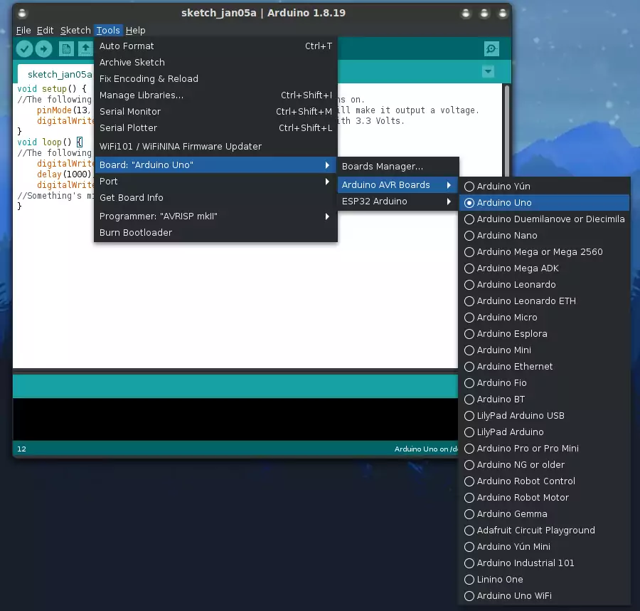
Let’s Start Coding! The First Arduino Code Sample
If the IDE hasn’t already created a new project for you, create a new one via the File menu and it should create two functions for you named ‘setup‘ and ‘loop‘. The code inside ‘loop’ is executed repeatedly and it never stops. Exercise caution with loops because they can cause hanging if they are not slowed down or controlled appropriately.
void setup() { //The following code will be executed once when your Arduino turns on. pinMode(13, OUTPUT); //Set pin 13 as an 'output' pin as we will make it output a voltage. digitalWrite(13, HIGH); //This turns on pin 13/supplies it with 3.3 Volts. }
The line of code starting with ‘pinMode’ sets pin 13 as an output. This enables us to write a value to the pin. The value can be ‘HIGH’ or ‘LOW’. HIGH turns the pin on and LOW turns it off. Therefore, to turn on pin 13, we need to write ‘HIGH’ to it as shown on line 4 using the ‘digitalWrite’ function. In the digital world, a binary value of 1 means HIGH or ON, and 0 means OFF or LOW. However, for Arduino we will stick with HIGH and LOW.
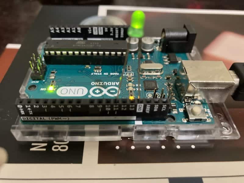
On the Arduino Uno board used for this example, pin 13 has an LED connected to it — therefore you should see a tiny orange LED on your Arduino switch on. Click the upload button in the IDE and wait for it to say ‘Done uploading’ before doing anything else.
The second code example is a little more interesting as it switches that pin on and off every 1,000 milliseconds (1 second). The orange LED will blink at one-second intervals…or will it?
void setup() { //The following code will be executed once when your Arduino turns on. pinMode(13, OUTPUT); //Set pin 13 as an 'output' pin as we will make it output a voltage. digitalWrite(13, HIGH); //This turns on pin 13/supplies it with 3.3 Volts. } void loop() { //The following code is executed repeatedly, as it is a loop. digitalWrite(13, HIGH); //Step 1: The LED Turns on. delay(1000); //Step 2: Wait one second. digitalWrite(13, LOW); //Step 3: Shut the LED off. //Something's missing here: The LED will immediately turn back on as there is no delay. }
Carefully read each line and think about what it will do. This practice helps you to visualize what your code does, which makes it easier to spot bugs. Immediately after the last line, the ‘loop’ function executes again like its supposed to, but there is no delay after the last line that turns it off, or before the line that turns it on.
This means that the LED will appear to stay on permanently because of how quickly this occurs.The solution to this problem is to add the following line after ‘digitalWrite(13, LOW)’:
delay(1000);
Now the LED will turn on for one second, and then turn off for one second, then repeat that cycle forever.
Dimming An LED: An Arduino PWM Example
Arduino kits come with a neat technology called Pulse Width Modulation (PWM) built in. PWM enables you to control the brightness of LEDs or control the speed of a motor instead of just switching them on or off. The possibilities are endless!
I can’t explain the full details of PWM and how it works in this article because it would be long, but I did write a separate article explaining how pwm works if you’re curious. The following Arduino PWM code sample reduces the voltage and average current output of pin 11:
void setup() { pinMode(11, OUTPUT); analogWrite(11, 127); //Operates at a reduced voltage and current. }
I connected a small LED to pin 11 to see the results of the above PWM code sample. As expected, it operates at a reduced brightness due to the lower voltage. The ‘127’ is a number that can range from 0 to 255, with 255 being the brightest setting. You can use this to set the ‘duty cycle’, which is explained in the PWM article I linked to above.
You can’t use the LED we used earlier on pin 13 for PWM, therefore we have to use pin 11 instead. Pins with a ‘~’ mark beside them on the Arduino support PWM. See if you can find a small LED to connect to pin 11 for this exercise.
The first parameter (where you see ’11’) in this PWM code sample just specifies the pin number you’re controlling, as is the case with the previous example. Play around with this and adjust the values, as well as observe the voltage across the LED’s pins while you’re doing it. The voltage can be observed with a multimeter or a voltmeter.
Reading From Arduino GPIO Pins: An Arduino GPIO Example With Buttons
Checking if a button is pressed (we will refer to this as the button state) on an Arduino entails reading the state of the pin that button is connected to. If the state is ‘HIGH’ then the button is being pressed, if it is ‘LOW’, then it is not being pressed. This is achieved using the ‘digitalRead‘ function.
The ‘digitalRead’ function returns that HIGH or LOW value we’re looking for, which means that you can simply assign that value to a variable of the integer datatype. The first step to reading an Arduino button state is to choose which pin we will connect the button to. For this example, we will use pin 11. Since a button is an input device, we need to declare its pin as an input (do this in the setup function):
pinMode(11, INPUT);
We also need to declare a variable to store the button state in. Let’s call it ‘btstate‘ and then assign the button state to it using the digitalRead function.
int btstate = 0; //To be declared outside of all functions as a global variable.
void loop() { btstate = digitalRead(11); }
Connect one of the button pins to pin 11 through a ~ 5 kOhm resistor, and the other pin to ground (GND). Press the button. You can now use ‘digitalWrite’ or other other functions to switch on an LED, relay, adjust PWM duty cycle (for example, increase the brightness of a lamp) whenever the button is pressed.
A simple way to test this is to use an ‘if’ statement to check the value stored in ‘btstate’ and then turn on an LED if it is ‘HIGH’ or turn it off if it is ‘LOW’. Note that the LED will only stay on while the button is depressed, and will shut off when you release it. Here’s the full source code:
int btstate = 0; void setup() { pinMode(13, OUTPUT); pinMode(11, INPUT); } void loop() { btstate = digitalRead(11); if (btstate == HIGH) { digitalWrite(13, HIGH); } else if (btstate == LOW) { digitalWrite(13, LOW); } }
Unfortunately, the LED may turn on when it is not supposed to due to a floating voltage on pin 11. To overcome this problem, you may need to connect a 1 Megaohm resistor between pin 11 and GND.
Serial Communication: A Way To See What Your Arduino Is Doing
Arduino has an incredibly simple and convenient serial communication library that enables you to transmit data over serial with only two lines of code! The Arduino serial library will be useful throughout these tutorials as it provides an easy way to display the result of your Arduino’s activities on your computer screen.
In this Arduino Serial example, we will write text to the Arduino serial port, which will send it over the USB cable to your computer, which will then display that text in a terminal window. In the ‘setup()’ function mentioned above, add the following lines to start the Arduino serial port and set it to a bit rate (otherwise called baud rate) of 9600 bps (bits per second) and print ‘Hello World’:
Serial.begin(9600); Serial.println("Hello world!");
The second line of code transmits ‘Hello World’ via the serial port (in this case, it will pass through the Arduino’s serial-to-USB interface so your computer can read it). This mean the serial port’s output is being piped to the USB port, and then to your PC.
To bring up the serial terminal and view its output, go to Tools >> Serial Monitor in the IDE. You should see something like this show up in the resulting serial console:
Hello world!
You can also move the second line of code to the ‘loop’ function so that it will be executed repeatedly and keep transmitting it. This is useful if you are monitoring something in real time such as voltage or a sensor reading.
You should see the ‘TX’ light on your Arduino blink whenever it transmits. That indicates that it is transmitting via the serial port. The ‘RX’ light indicates that it is receiving a serial transmission. Learning how to use the Arduino serial interface could be one of the single most helpful things you do.