By Nicholas Brown – Follow me on Twitter.
The Silicon Labs EFM8 microcontroller development kit features an 8-bit EFM8UB1 MCU (the ‘UB’ means Universal Bee) based on the commonly-used 8051 core, which can be used to create many inventions!
Its IDE — Simplicity Studio, comes with example code to demonstrate a variety of tasks, including one that can blink an LED. If you’re like me, and you learn better with tutorials that break down explanations into their simplest terms, then you will find this EFM8 tutorial helpful.
If you’re new to microcontrollers, you should find this EFM8 GPIO tutorial helpful as well. Little to no experience with microcontrollers or embedded systems is assumed. However, basic electrical and programming knowledge are assumed. As always, prior knowledge of embedded systems is helpful, and knowledge of the 8051 is even more helpful.
One of the first things you may want to do after purchasing a microcontroller development kit is try out the example code or preinstalled demo programs. I encourage you to do so, and start with the one titled ‘Blinky Simple’. Blinky Simple is a simple, brief project that demonstrates the use of GPIO and timers. Example code is very useful, but a tutorial can make a world of a difference to a beginner.
Before we get started, MCU means microcontroller unit, but you can just call them microcontrollers. A microcontroller is normally built for the purpose of controlling hardware and processing signals received from sensors (for example, converting a temperature sensor’s voltage reading into a more useful metric, like degrees). Microcontrollers are embedded systems themselves, and are frequently incorporated into larger embedded systems for various reasons.
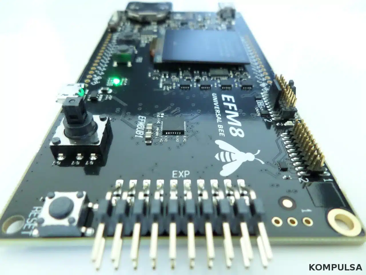
In many cases (including the EFM8UB1), a microcontroller is also sold as part of a development kit like the 8051-based SLSTK2000A pictured above. The EFM8UB1 MCU is that tiny little 28-pin chip beside the EXP pins. The starter kit (the SLSTK2000A) provides a convenient interface through which you can easily plug it into your computer’s USB port, plug peripherals into it, and more without requiring any exotic tools.
Tip: Whenever working with a microcontroller, it is helpful to have its reference manual or datasheet on hand.
EFM8 GPIO Basics – What Is GPIO?
To start this EFM8 tutorial, we’ll learn GPIO. GPIO operations are among the simplest one can do on an MCU.
GPIO is a common acronym used in the microcontroller sphere to refer to input and output operations, including the two simple but incredibly useful tasks of switching pins on and off and detecting when a button is pressed. GPIO stands for General Purpose Input and Output.
A GPIO pin is one that can be ‘driven’ HIGH or LOW (often referred to as a logic high/logic 1 or logic low/logic 0, respectively) using a microcontroller (these are built into virtually all MCUs) to perform tasks such as switching a relay or transistor on or off (although you may need to use a transistor to do this without damaging your MCU).
This means you can use GPIO pins to switch appliances on or off, switch components of your appliances such as heating elements and fans on/off, generate PWM signals to control the speed of fans and other devices using motors (which I explain how to do here), and much more. This is part of what makes microcontrollers so exciting!
In some cases, a GPIO pin may be referred to as a ‘bit’, and the bit number corresponds to the pin number. For example, pin 1.6 may be referred to bit 6. Note that the 1 in 1.6 is the port number. So 1.6 means Port 1: Pin 6, or Port 1: Bit 6. Your EFM8 SLSTK2000A kit has its pin numbers printed on the board in the same format (for example: 3.1, 1.5, 2.2), as shown below.
If you don’t want to solder pins to your new EFM8 kit, you’re not alone. You can use the pins in the expansion header marked EXP shown at the right of the photo (the EXP pinout is shown in the User’s Guide [PDF]), but purchase a pack of jumper wires (otherwise known as pin plugs) to facilitate easy/safe connections first (this can help to prevent accidental shorting).

HIGH means ON, and LOW means OFF. A value of 1 means ON, and a value of 0 means OFF. To switch on a pin/bit, you write a value of 1 to it. To switch it off, you write a value of 0. In the case of some MCUs, you may need to manually configure the pin/bit as an output (set it to the output direction to supply or source current). Setting it to the input direction is applicable if you need the 8051 MCU to read from the pin. In such a case, the pin would be sinking current from a small current source such as a button connected in series with a power supply, or a digital sensor.
When a pin is ON/HIGH on the EFM8UB1 (and most other MCUs), it will supply (source) a very small current dependent on the resistance of your circuit (often in the order of microamps and milliamps, denoted by the uA and mA symbols respectively) at 3.3 volts. In the case of the EFM8UB1, the maximum amount of current that can be sunk or sourced by any I/O pin is 100 mA (according to page 30 of the datasheet [PDF]). Due to this small current capacity, you can’t just connect a light bulb or fan directly to a microcontroller.
I would recommend keeping it under 20 mA to be on the safe side. You need a driver for those things. Fortunately, a driver could consist of two simple parts — a transistor and a resistor. The transistor would play the role of an amplifier so that you can control large items like appliances or automobiles without frying your beloved new MCU. The resistor would the reduce the amount of current flowing from the MCU to the transistor to protect them both.
GPIO pins can also be driven high or low using a device external to your microcontroller, such as a button. In this case, the microcontroller may interpret a depressed button as a HIGH signal, and a released button as a LOW signal.
You can learn more about the various units of energy, like the microampere in the energy units section.
Let’s Start By Turning On A GPIO Pin
Download and install Simplicity Studio from the Silicon Labs website. Simplicity Studio is an integrated development environment (IDE), which we will use to configure our EFM8 microcontroller’s peripherals, write our source code, and upload our project to the MCU. If you haven’t already, purchase the EFM8UB1’s starter kit (the SLSTK2000A).
If you’re using the Linux version, detect your device in Simplicity Studio by selecting the Solutions tab, then click Add Devices as shown below. When the device detection screen comes up, slide the white switch beside the battery holder over to the AEM position. Afterwards, plug the provided USB cable into the USB port at the left of the board, and plug the other end into your computer’s USB port. Wait a moment.

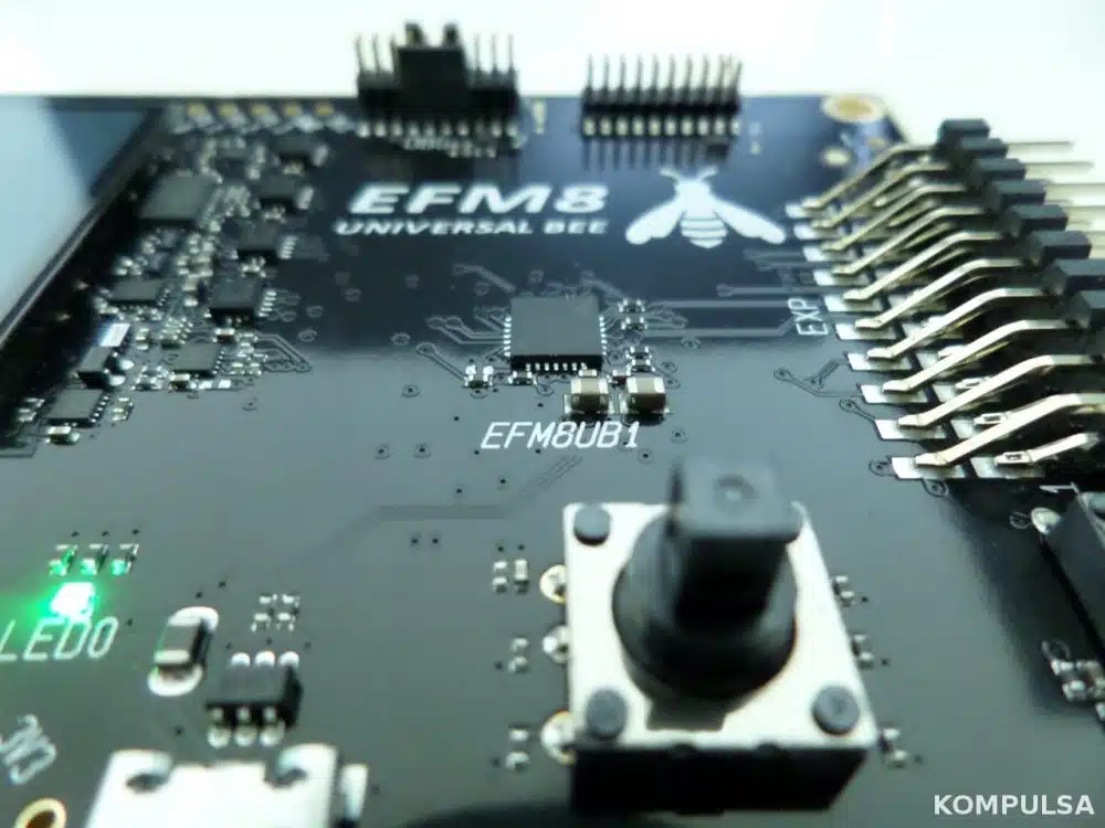
Your EFM8 should show up in the ‘Detected Devices’ list. Check it and click OK. To be sure, look at the MCU (which has EFM8UB1 printed under it as shown below, and you may need a magnifying glass) to get the full model number.
Now you can go to the ‘Devices’ tab and select your device. The device shown under that tab should be the one you just added. Proceed to create a new project by clicking ‘New Project’. You will be asked to select a device. If it hasn’t already selected it for you, click the dropdown box and select the EFM8UB1.
Click ‘Next’ and then ‘Yes’ to allow it to download the Configurator data. Check the ‘Empty C Program‘ radio button, and name the project ‘HelloWorld’, then click ‘Finish’.
In a moment, you should see your main source file — main.c in the editor. Inside the main function called ‘int main()’, type the following between the braces (these two: { }) to enable Crossbar and switch on Pin 7. Ensure that the following code is above the while loop, and not inside it. Or you can just delete the while loop code, as it isn’t needed for this exercise. Comments are grayed out and denoted with a ‘//‘.
XBR2 |= 0x40; //Enable Crossbar so we can easily turn pins on and off.
P1_B7 = 1; //Write the output value of 1 to Port 1: Bit 7, turning pin 1.7 on.
That was incredibly simple code, but there are other things you may want to do, to save energy. For example, switching off unused pins. Also bear in mind that if using some other MCUs, you may be required to set pins to the output direction before you can write to them.
Switch off all the pins on port 1 and port 2 to save energy as shown below, as they are switched on by default. Pin 1.7 is the only one you need for this exercise.
P1 = 0; //Switch off all pins on port 1. Don't worry, the P1_B7 = 1 code above will switch pin 7 back on.
P2 = 0; //Switch off all pins on port 2.
After switching off the pins on port 1, the RGB LED connected to pins 1.4, 1.5, and 1.6 will switch on, but those pins will actually be off. Don’t worry about that. It’s because that particular LED is designed to switch on when those pins are ‘low’ or ‘off’.
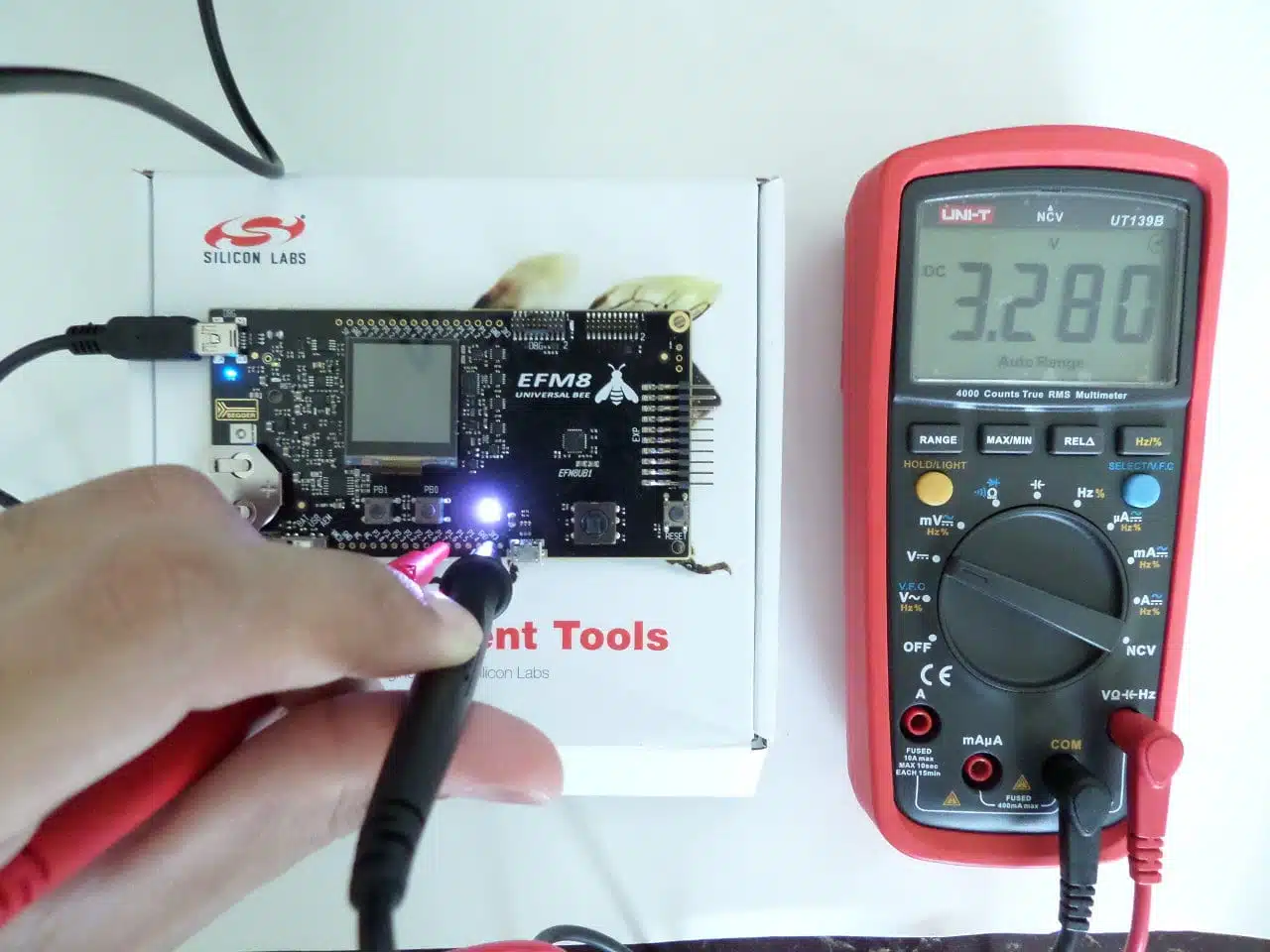
Use a voltmeter or multimeter to check the voltage across pins 1.7 and GND, and you should get a reading of 3.3 volts.
Your main file should now look like this (excluding the comments generated by the IDE, which I would recommend reading):
#include <SI_EFM8UB1_Register_Enums.h>

int main (void)
{
    XBR2 |= 0x40;
    P1 = 0;
    P2 = 0;
    P1_B7 = 1;
}
To turn the pin back off, just change that ‘P1_B7‘ = 1; line to ‘P1_B7‘ = 0;.
If you wanted to blink an LED or generate a PWM signal, you could use one of the built-in timers, and in an interrupt service routine: alternate the value assigned to the register P1_B7 between 1 and 0 every time the timer ‘overflows’. An article explaining how to do that is on its way.
A More Readable Alternative
Place the following code in your int main function, replacing the code above:
SI_SBIT(FAN, SFR_P1, 7);

FAN = 1;
The ‘SI_SBIT’ line essentially assigns the name FAN to Pin 1.7. SFR_P1 refers to ‘Special Function Register’, port 1. Remember what we learned about ports! FAN = 1 turns on the pin which we named ‘FAN’. Example: If this pin is being used to drive a transistor controlling a fan, the fan will turn on. To turn the fan back off, simply type ‘FAN = 0’;
To clarify the syntax:
SI_SBIT(YourPreferredName, SFR_PortNumber, PinNumber);
Coming Soon: Using The Timer To Blink An LED And Adjust Its Brightness.