In my previous tutorial, I explained how to use the HET pins to generate a PWM signal with only a few lines of code using the TMS570 MCU evaluation kit. In that tutorial, I explained how to adjust the brightness of an LED using PWM, as well as how to blink it. In this tutorial, i’ll show you how to use the simple General Purpose Input/Output (GIO/GPIO) pins (the ones on GIOA, which can also be called GIO Port A) to switch an LED on and off using a button.
The GIO interface (often called ‘GPIO’ in other embedded systems) is even easier to work with, but it doesn’t have that convenient built-in PWM functionality that the N2HET pins do. It’s good to learn GIO, though. Many MCUs have a GPIO interface.
The TMS570LS043x Launchpad evaluation kits come with a button connected to the GIOA pin 7 (marked on the Launchpad as GIOA7), which you can configure to your heart’s content, and an LED connected to GIOA bit 2 (marked GIOA2 on the TMS570 Launchpad). In this tutorial, you will enable the GIO driver, set the button GIOA7 to the input direction, enable the interrupt for the LED/bit GIOA2, and finally write your code to turn on that LED as shown below.
Preparing Your HALCoGen And CCS Projects
First, create a HALCoGen project. Go to File > New > Project, and select the TMS570LS04x MCU. You’ll see two options: The TMS570LS04x and it’s FreeRTOS equivalent. For this tutorial, we will select the first option, TMS570LS04x and choose an appropriate directory. Proceed to the tab corresponding to your MCU’s model number (TMS570LS0432PZ in my case). Select Enable GIO driver, as shown below.
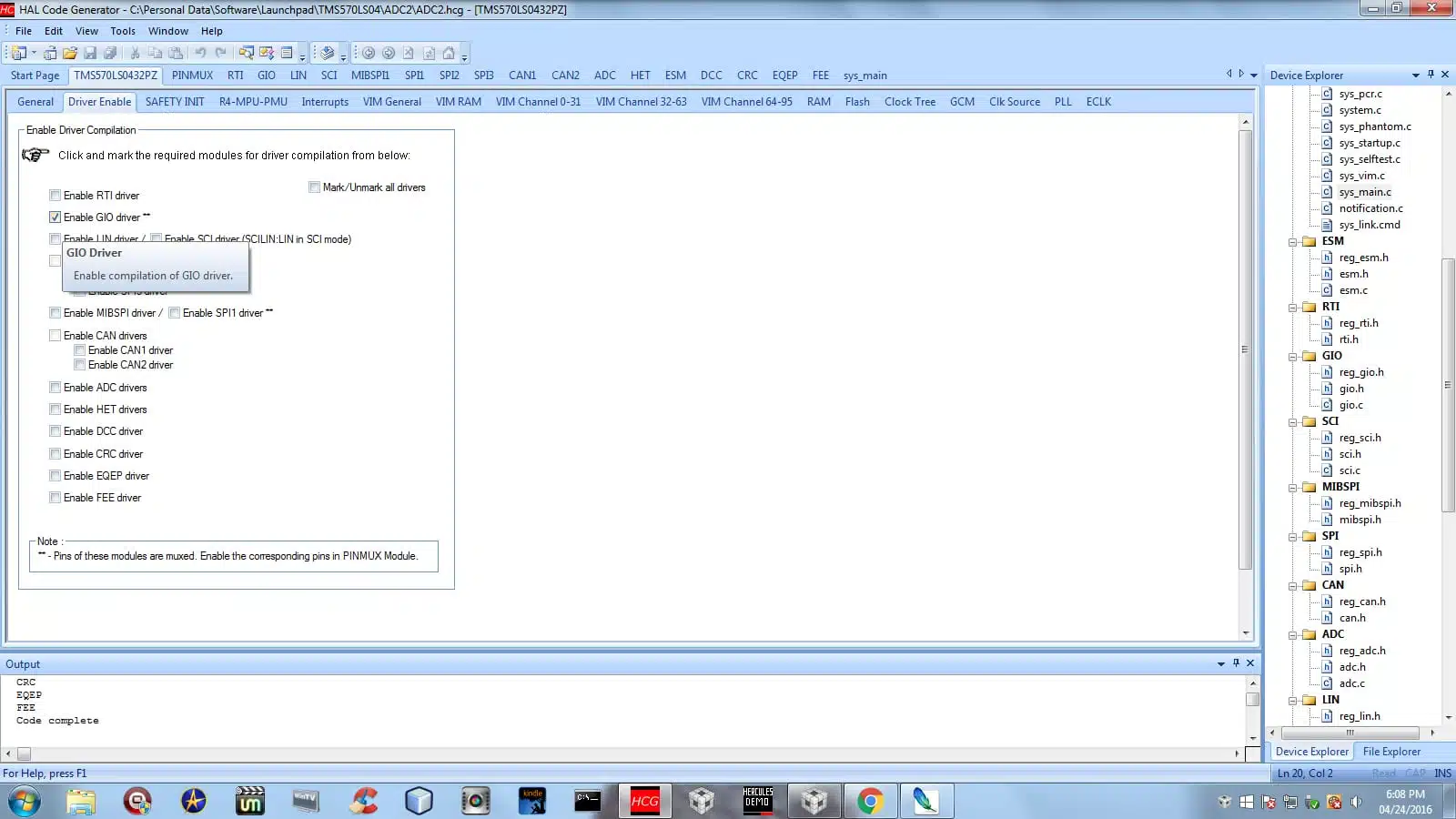
Next, proceed to the GIO tab and enable the interrupts for GIOA bits 2 and 7 on your TMS570. The interrupt required to turn on the LED GIOA2 is now enabled.

Setting bit 2 to the ‘output direction’ just means that it is going to write to that bit instead of reading from it. To turn it on, we will simply set the bit’s value to 1. To a computer, 1 means on, and 0 means off. The DOUT dropdown box is there so that you can have HALCoGen generate the code to turn it on for you, but we’ll leave it off (DOUT: 0) for now because we want to turn that LED on only when we press the button connected to GIOA7.
The next step is to click ‘Generate Code’ under the file menu (or press F5) and set up Code Composer Studio (CCS). If you have already obtained a copy of CCS, launch it and set your workspace to the same directory that your HALCoGen project directory is in, not to the HALCoGen project directory itself. If your HALCoGen directory was set to. Be sure to select the TMS570 (the TMS570LS04x, unless you’re trying this with another model) MCU when creating your project.
For example, if your HALCoGen project directory is C:\Hercules\Giotest, you would set your CCS workspace to C:\Hercules and then create a new CCS project called Giotest in that directory. Your CCS project should have the same name as your HALCoGen project, as they will share the same directory. You may need to update your settings/generate new code in HALCoGen from time to time without repeatedly copying all those files.
Finally, go to File > Properties > Include Options, then click the green plus sign and add the include directory in the Giotest directory.
Finally, Let’s Start Coding!
Type the following in sys_main.c in CCS (located under /source), and type it between the user code comments as shown below so that HALCoGen doesn’t overwrite it:
/* USER CODE BEGIN (1)  */

#include "gio.h"

/* USER CODE END */

void main(void) {

/* USER CODE BEGIN (3) */

gioInit();
while(1) {
    if (gioGetBit(gioPORTA, 7))  {
        gioToggleBit(gioPORTA, 2U);
    }
}

/* USER CODE END */

}
It is actually one line of code that turns the LED on or off — gioToggleBit(gioPORTA, 2U);.
That toggles bit 2’s (referred to as 2U in this case) output value between 1 and 0. The ‘2’ in 2U is the bit number. You can change that to whichever GIOA pin number you see on the TMS570 board that you want to control. So if you decide you want to toggle the pin GIOA6, just change the 2U parameter to 6U.
As for the other lines of code — They get the value of GIOA7 (which corresponds to the button’s state). When the button is depressed, the value of GIOA7 (otherwise known as bit 7), is 1. So it’s on. Otherwise, its value is 0 (off). gioGetBit() simply gets the value of the button and returns a 1 or 0 to the if statement. The while loop is used so it keeps checking to see if the button is being pressed.
Code tested with CCS version 6.1.1.00022.