By Nicholas Brown.
The Raspberry Pi is a single board computer (SBC) that has some microcontroller-like capabilities (most notably basic GPIO), however it runs Linux (or optionally other operating systems) on its ARM processor. This code is for Raspberry Pi 3 Models in general. However it has only been tested on the 3A+ and 3B.
Let’s start with a quick overview of GPIO. GPIO means General-Purpose Input/Output. A GPIO operation is the process of switching the power to a GPIO pin on or off. A GPIO pin can be used to toggle a large switch such as a relay (with the help of a transistor), so you can switch on an appliance using your Raspberry Pi, or control it via PWM so you can dim a light bulb or control the speed of a motor.
I explain PWM and what it can do here.
| Table Of Contents |
| Turn On An LED Using A GPIO pin. |
| Don’t Exceed The Current Limit. |
| Blink An LED. |
| Dimming The LED: A PWM Example. |
| GPIO Read Operations: Detecting If A Button Is Pressed. |
Fun Raspberry Pi Projects You Could Build With GPIO:
- Automatically switching on your washer or clothes dryer at certain times of day (one idea is to switch them on during off-peak hours to take advantage of cheap electricity).
- Switching off lights at dawn.
- A remote-controlled dimmable light bulb (your can set up your phone as the remote with an Android or iOS app).
This Raspberry Pi GPIO tutorial will use the WiringPi library and the C programming language. The first code sample will simply turn on an LED. The first step is to install the WiringPi library. This is a C library that you can download and install with the help of Git. Git is something you’ll want to have when working with Linux or developing software.
Install Git and Git Core by typing:
sudo apt install git git-core
‘sudo’ is not required if you’re logged in as the ‘root’ user. However, it is inadvisable to login as root.
Now ‘cd to whichever directory you want to download the wiringPi code to. You will then run the following Git command and then a build script that will install it in the appropriate directories for you. Type the following two commands:
git clone git://git.drogon.net/wiringPi
cd wiringPi
./build
Raspberry Pi Sample Code: Basic GPIO – Turning On A Pin
This code sample has been tested on both the Raspberry Pi 3B and the 3A+. It might work on others, but I haven’t tested it on those yet.
If you’d like you can download this Raspberry Pi GPIO code sample to your Raspberry Pi if you don’t have a GUI installed (convenient if you’re using the Raspbian Lite or DietPi OS) via command line using the following wget command, after which it will download the code to whichever directory you’re currently in:
wget kompulsa.com/samplecode/rpi/gpio.c
I highly recommend rewriting the code from memory afterwards, and change it up a bit to see what happens!
#include <wiringPi.h>

int main(void) {
	wiringPiSetup();
	pinMode(0, OUTPUT); //Configure Pin 0/BCM 17 as an output.
	digitalWrite(0, HIGH); //Turns on Pin 0/sets it 'high'.
	return 0; //Exit the program, returning error code '0';
}
BCM means ‘Broadcom’. Broadcom is the brand of the System-on-Chip (SoC) that powers your Raspberry Pi (the model number is BCM2837 for the Pi 3 model A and B). That contains the processor among most of the other parts in your Raspberry Pi. ‘BCM 17’ just means ‘Broadcom pin 17’. BCM 17 is a GPIO pin.
‘0’ Corresponds to BCM 17, which is physical pin 11 or pin 0 if using WiringPi. The GPIO pin number you use in the code is determined by the library you use. Don’t worry too much about this, as we are using only one library in this GPIO tutorial (WiringPi).
‘HIGH’ (otherwise called a ‘logic HIGH’) means ‘on’ (which to the Raspberry Pi is a ‘1’). When a pin on your Pi is on, it’s 3.3 volts. LOW means ‘off’ (which is a ‘0’ to the Raspberry Pi). When a pin on your Pi is switched off, it is 0 volts. It’s digital, so there is no voltage between 0 and 3.3 Volts, however PWM enables you to simulate the effect of voltages in between those two, such as 2.0 volts or 3.1.
Why the name ‘digitalWrite’?
The ‘write’ in digitalWrite means that it is writing a value to the pin that we set as an output (WiringPi Pin 0). This value can either be a 1 or a 0. UART and similar digital communications devices write a series of ones and zeroes to their pins to transfer data. To be more specific, they convert data the data you want to transmit to ones and zeroes, and then write those ones and zeroes to a GPIO pin.
Compile the program using a C compiler such as GCC (install it with sudo apt install gcc if you don’t already have it):
gcc gpio.c -o gpio -lwiringPi
Now run it:
./gpio
Identifying The Pins
You can find a pin by looking at the Raspberry Pi 3 GPIO pinout and see which pin on the board it is by looking at this page which has an interactive image showing where each pin is located. I find it convenient to count how many pins from the right it is.
The Raspberry Pi GPIO pins are not designed to supply power, they are for signalling purposes, meaning that they serve the purpose of switching on a larger switch such as a transistor or relay using a very small current (you’ll find that you won’t have to draw more than a few mA from your GPIO pins when you become accustomed to setting up these switching circuits).
Analogy: Think of the Raspberry Pi as a truck driver, and the transistor and/or relay is the power steering system with the muscle to turn the wheels/switch large appliances on or off.
A few examples of acceptable configurations (always read and work within transistor and relay ratings):
GPIO pin -> Transistor -> Relay -> AC or DC light bulb.
GPIO pin -> Transistor -> DC fan (transistors are for DC only, triacs can work for AC).
GPIO pin -> Transistor -> Relay -> Clothes dryer.
GPIO pin -> Transistor -> Relay -> Heater.
Raspberry Pi Current Limitations
Drawing more current than the Raspberry Pi is designed to provide will damage it. This is called overloading. You can draw up to 16 mA from a given GPIO pin on your Raspberry Pi. Exceeding that is likely to damage your Raspberry Pi.
A few examples of things that will overload your Raspberry Pi if directly hooked up to it without a transistor or op-amp circuit:
- Fan.
- Light bulb.
- Relay (some tiny relays designed for this may be an exception).
- Heating element.
If switching on a relay instead of the LED (another fun idea!), ensure that you use the Raspberry Pi to switch on a suitable transistor and then have that transistor switch on a relay. This is why discrete LEDs are so convenient for these first-time projects, as they draw very little current!
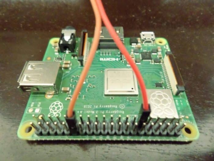
Hook up only a discrete LED to physical pin 11/WiringPi pin 0 (an easy one to find is one of those tiny green or red LEDs used to illuminate buttons). Connect the LED’s longer lead/terminal to pin 0, and the shorter lead to one of the GND pins. Run the program and the LED will turn on.
To turn the LED back off, you would change the ‘HIGH’ in the ‘digitalWrite’ line to ‘LOW’. That’s it!
Blinking An LED: A More Advanced Raspberry Pi GPIO Code Sample
You can modify your code to blink your LED every second by setting the pin high for a second, then setting it low for another second. Put that code in a for loop and it will keep blinking, just like an automotive indicator!
For your convenience, you can download the blinking code sample via the command line and test it out right away:
wget kompulsa.com/samplecode/rpi/blink.c
Compile and run it using the same two lines of code shown in the previous example, just change ‘gpio’ to ‘blink’ and ‘gpio.c’ to ‘blink.c’. Your LED should now blink at 1-second intervals. If you want to blink the LED faster, just change the 1000 ms delay to a shorter one. So instead of delay(1000);, you can switch it to delay(500); to make it blink twice as fast.
#include <wiringPi.h>

int main(void) {
	wiringPiSetup();
	pinMode(0, OUTPUT); //Configure Pin 0/BCM 17 as an output.

	for(;;) {
		digitalWrite(0, HIGH); //Turns on BCM 17/your LED.
		delay(1000); //Delay by 1 second before executing the code below.
		digitalWrite(0, LOW); //Turns off the LED.
		delay(1000); //Another 1 second delay to keep the LED off for 1 second.
	}
	return 0;
}
Bonus: Let’s briefly dip our toes in PWM and dim our LED!
PWM is actually very simple, all you do is ‘blink’ the LED so fast that you can’t actually see it blinking, and then adjust the interval (delay) between blinks to control its brightness. The code below dims the LED to a 20% duty cycle.
This means the LED is on 20% of the time, and off 80% of the time. Change the first delay in your code from ‘1000’ to ‘1’ as shown below. This is how long the LED will be on (1 ms). Next, change the second delay to ‘5’. This is how long the LED will be off.
#include <wiringPi.h>

int main(void) {
	wiringPiSetup();
	pinMode(0, OUTPUT); //'0' Corresponds to BCM 17, which is physical pin 11 or pin 0 if using WiringPi.

	for(;;) {
		digitalWrite(0, HIGH); //Turns on BCM 17/the LED.
		delay(1); //Delay by 1 ms. LED will be on for 1 ms.
		digitalWrite(0, LOW); //Turns off BCM 17.
		delay(5); //A 5ms delay. The LED will be off for 5 ms.
	}
	return 0;
}
To brighten the LED, you would simply increase the amount of time it is on, relative to the time it is off. To increase the brightness of the LED, just shorten the second delay time and increase the first delay time. What this means is the LED will stay on longer, and will be in its off state for a shorter time period.
The ‘delay’ function isn’t the ideal way to do PWM, as the Raspberry Pi already has built-in PWM capabilities that don’t require you to use those delay functions. This was the manual way to do it! I did it to show you how PWM really works, and just how simple it really is.
pwmWrite Example: Using The Raspberry Pi’s Built-In PWM Function
The method using the loop above enables you to use any GPIO pin you wish. However, if you only need to use one, it’s much easier to use the official PWM function in wiringPi’s library, which enables you to do PWM on your Raspberry Pi with only one line of code.
As always, you can download the example below on your Raspberry Pi using the following command for your convenience:
wget kompulsa.com/samplecode/rpi/pwm.c
#include <wiringPi.h>

int main(void) {
    wiringPiSetup();

    pinMode(1, PWM_OUTPUT); //Set this GPIO pin (1) as a PWM output.

    pwmWrite(1, 512); //Now we can dim the LED or slow down a fan via  PWM.

    return 0;
}
The ‘512’ is the PWM period (how long the power will be ‘on’). It can be a value ranging from 0 to 1024. A higher value corresponds to a higher duty cycle or brighter LED/higher fan speed.
Compile it using the same gcc code above, just ensure the source filename and output filename are correct (‘pwm.c’ and ‘pwm’ respectively).
Learn more about PWM and duty cycle on Kompulsa.
Reading From A GPIO Pin/How To Detect When A Button Is Pressed On Your Raspberry Pi
Aside from generating output/switching pins on or off, the other most frequent GPIO activity is reading from a pin. Remember what we learned above about writing values such as ones and zeroes to GPIO pins. It applies to this, but in reverse.
Let’s say we want to use a typical push button to switch on our LED. We would do this by connecting the button between a 3.3 Volt current source (the pin called ‘3v3 Power’) and a GPIO pin (which will be WiringPi pin 2, in this case).
The rest of the WiringPi pinout
Please ensure that you have a resistor connected in series with the button to avoid shorting the ‘3v3’ pin to the GPIO pin.
Pressing the button will then drive that input pin ‘high’. When it is released, that pin will go back to its ‘LOW’ state. We will use the ‘digitalRead‘ function to determine whether the pin is in a high or low state.
Each GPIO pin can be configured to operate as an input or output, so when I say ‘input pin’, i’m just referring to any GPIO pin configured as an input.
Feel free to download the example below using the same wget command as above:
wget kompulsa.com/samplecode/rpi/readpin.c
Raspberry Pi Example Code: Read From A GPIO Pin
#include <wiringPi.h>

int main(void) {
int pinval = 0;
wiringPiSetup();
pinMode(0, OUTPUT); //Sets Pin 0 (LED) to output direction so we can turn it on.
pinMode(2, INPUT); //Sets Pin 2 (button) to the input direction so you can read from it.

for(;;) {
    pinval = digitalRead(2); //Get the pin state (which is 1/on or 0/off).

    if (pinval == 1) { //If the pin is on, then:
        digitalWrite(0, HIGH); //Turns on the LED if the button is pressed.
    } else { //Otherwise
        digitalWrite(0, LOW); //Turns the LED back off if the button isn't being pressed.
      }
}
    return 0;
}
Now that you’ve gotten an idea of how easy it is to implement a button, you may have noticed that the LED doesn’t stay on once you have released the button.
If you don’t desire this kind of behaviour (which is often the case, actually) then you can rewrite that function to toggle a boolean or other variable whenever the button is pressed. That way, the LED will come on and stay on if you press the button, and go off and stay off if you press it again.