In this article, I’ll show you how to build a pwm fan controller (DC) using a brief C program, and a few parts including the Launchpad RM57L microcontroller development kit. It enables users to efficiently vary the speed of PWM fans to reduce noise levels, and power consumption. This project automatically monitors the temperature of the object the temperature sensor is attached to (in this case, a CPU heat sink used to cool a small thermoelectric module), and controls the fan speed accordingly to minimize noise output, as well as power consumption. Below is a demo of the fan controller in use on a desktop CPU cooler.
Video: Kompulsa.
Before learning how to build a fan speed controller, it helps to learn how the various speed control methods work. I will explain two key technologies: Resistive speed controllers and PWM fan controllers.
Resistive Speed Controllers
Resistive speed controllers control a given fan motor’s speed by resisting the flow of current from the power source to the motor. This can be done using a combination of a potentiometer and transistor, or another varistor circuit. The former technology is extremely easy to build, but causes the transistor to burn off quite a bit of the current passing through it. Therefore it is inefficient. PWM on the other hand, pulses the full current on and off many times per second. The transistor will still waste some electricity, but not as much.
PWM Speed Controllers
Pulse width modulation is a far more complex, superior, and an increasingly common current control method which facilitates the control of motor speeds, lamp brightness, among other things in an energy-efficient manner. Key reasons for PWM motor controllers include improving the efficiency of appliances, as well as reducing noise levels by operating them at low speeds whenever feasible.
I used the TI Launchpad RM57L MCU development kit to construct this fan controller (thanks to TI for sending it), but this code can be easily modified to run on the cheaper Launchpad TMS57012, or the Launchpad TMS57004 Launchpads as well.
When learning how to construct a pwm fan controller, it helps to understand or learn how to execute the various technologies/methods as well as their merits and disadvantages. This way, you’ll know exactly which to use, and when.
This article assumes that you have some electrical engineering experience, and know how to safely connect the transistor, sensor, and all the other equipment mentioned. Try this project at your own risk.
Table Of Contents
Parts List
All prices are in USD.
- 2n6284G NPN Darlington BJT Transistor. BJT means bipolar junction transistor (convenient because it has a DC current gain of 750).
- Three 12 kOhm 1/2 watt resistors.
- Junction box with screw terminals or bar connector.
- Texas Instruments Launchpad RM57L MCU (RM57L843) development kit.
- 10 kOhm NTC Thermistor with a B value of 3435. ‘NTC’ means that it’s resistance decreases whenever it’s temperature increases.
- 40mm x 40mm (or larger, if you can’t find that size) heat sink for the transistor.
- Jumper wires/pin plugs to connect the development kit’s pins to the transistor, and to connect the transistor to the power source (unless you’re using a breadboard). These are usually in the $3-6 range.
- 12 or 5 volt power source.
- 12 volt CPU fan, or a 5 volt laptop fan (this project is intended for three or four-wire fans that support PWM). These are typically in the $10-$20 range.
- CPU cooler (with a heat sink and fan included) or any other combination of a fan and a hot object that can be cooled with it. This enables you to watch the fan controller automatically cool itself off, and shut the fan off. I used a CPU cooler with a built-in fan. It’s the ultimate test!
I would recommend attaching a heat sink to the transistor if you’re going to power large fans (larger than the tiny 80mm fans that are typically used for desktop CPU cooling). It will generate a significant amount of heat.
Prepare Your Development Environment
The RM57L843 development kit is the heart of this PWM fan controller (the way these microcontrollers work isn’t much different from an Arduino, so don’t be intimidated!). Our first step to building this pwm fan controller is to set up our development environment which we will use to program/flash the MCU.
Plug the Launchpad RM57L development kit into your computer’s USB port using the cable provided, and then create a Texas Instruments account so you can download the CCS IDE. We will also use HALCoGen for this exercise. HALCoGen is a HAL code generator that enables you to easily configure your MCU using a GUI. In this case, we will use it to configure the analog-to-digital converter (the MibADC), and the HET timer module.
Download HALCoGen and CCS (ensure that you’re logged into your TI account for CCS), and then follow the instructions below to create your HALCoGen project.
First, create a new project in HALCoGen, select the ‘RM57Lx’ development kit, and then you’ll see a list of its variants to the right of the screen. In this case, there is only one variant: The RM57L843ZWT. Select that and name your project ‘PWM’ as shown below. Enter the project’s path in the ‘Location‘ field, make a note of it, and click OK. We will store our CCS project in the same directory. Your PWM project should be located in a folder named PWM, under your working directory, which we will name RM57L.

Create a new project called ‘PWM’ in HALCoGen. This is where you configure the ADC and HET modules.
In order to build a PWM fan controller, you need to set up timers that will oscillate a small electrical on and off, and set their frequency.
Next, enable the ADC1 and HET1 drivers by selecting the ‘Driver Enable’ tab, and checking the boxes as shown below. The analog to digital converter (ADC) will be used to convert the analog temperature sensor reading to a digital value we can use to determine the temperature, enabling the fan controller to adjust the fan speed accordingly. The high-end timer (HET) will be used to generate our PWM signal, which will be used to control a simple BJT transistor.
I recommend unchecking the rest of the drivers to conserve system resources (for example: RAM and flash memory).

It is now time to configure our pwm fan controller’s analog to digital converter (which is built into the Launchpad RM57L MCU). Go to the ADC1 tab and set the FiFo size to 1, as that’s all we’ll need for this project. Also select Enable Pin 7, as that is what we will connect the temperature sensor to. Pin 7 is marked ‘AI1_7‘ on the underside of your Launchpad development kit.
How Analog To Digital Conversion Works

Proceed to the HET1 tab where you’ll configure our fan controller’s PWM timer (built into the RM57L development kit), and the HET pin that controls the transistor powering the fan and do the following as shown in the next screenshot.
Select the Pwm 0-7 tab, set the Duty [%] field for PWM 0 to 0. That sets the duty cycle of the PWM signal to 0, hence setting the duty cycle of the fan you’re controlling to 0. A duty cycle of 0 simply means that the fan will be off. Another way to put it is: The percentage of the time that the power will be on is 0.
We will start with a duty cycle of 0 in this project because we’re going to programmatically adjust the duty cycle (and hence, the fan’s speed) in such a way that it follows the temperature of the heat sink the temperature sensor is attached to. When the duty cycle is set to 0, the fan controller will turn the fan off (0 corresponds to 0%). Next, check the pair of ‘Enable’ checkboxes just to the left of the ‘Pin‘ field. That enables the PWM signal. Enter 2 in the ‘Pin’ field, which is HET port 1, Pin 2, marked ‘HET1_2’ on the underside of your Launchpad. Finally: enter 10,000 (without the comma) in the Period[us] field.
The unit used in this field is the microsecond. A microsecond is one millionth of a second. Setting this field to 10,000 will make the HET timer cycle the power on and off every 10,000 microseconds (every 0.01 seconds). Due to this rapid switching, you won’t notice that the power is being switched on and off, resulting in smooth, continuous operation of the fan.

Enable the timer ‘PWM 0’.
To wrap up HALCoGen configuration, select the Pin 0-7 tab. This is where you’ll configure the RM57L pin that the transistor’s base will be connected to (through the 12 kOhm resistor, of course). Check the DIR checkbox in the ‘Bit 2’ section as shown below to set bit 2 to the output direction. This enables us to turn the fan on. A pin may be referred to as a bit, so ‘Bit 2’ in this case means HET Pin 2.
The output value (marked DOUT in the screenshot below) is the state of the pin, which can be either on (1), or off (0). Ensure that it is set to 0, so its off when the MCU initially starts up.

Set HET1, Pin 2 to the output direction.
Select File > Save Project, and then File > Generate Code (or press F5). Watch the ‘Output’ pane at the bottom until it says that the code generation is complete. Now you can move onto the CCS configuration, and when you’re done, you can finally gather the parts and build the fan controller.
Let’s Code!
Launch CCS and select/create a directory named RM57L as your workspace as shown below. Create a new project in Code Composer Studio called PWM, which will be saved in the root of the PWM directory where you will see the PWM.hcg file. PWM.hcg is your HALCoGen project file. As I said above, the CCS and HALCoGen projects files are to be in the same directory for this exercise.
Plug in your Launchpad RM57L development kit using the provided USB cable.
To your right, select ‘RM57L8x’ from the dropdown box, as that is what we’ll be using. Next, select the XDS110 USB debug probe from the dropdown box below it. Finally, select ‘Empty Project’ and click Finish.

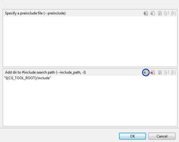
Right click the PWM project in the Project Explorer pane (it’s on the left side of the screen), then add the HALCoGen /includes folder from your PWM project directory to your CCS project by clicking the button circled below. These RM57L include files consist of libraries and drivers which make it much easier to write programs for the MCU.
Navigate to the HL_sys_main.c file in the Project Explorer Pane to the left under /PWM/source/. In that file, paste the RM57L code sample below.
The Source Code (Hercules RM57L Code Sample)
The following RM57L sample code can be uploaded to your Launchpad via USB using Code Composer Studio. This is how your source file should look:
Temperature readings are in °C.
HL_sys_main.c
/* USER CODE BEGIN (1) */
#include "HL_het.h" //The HET library we'll use for PWM.
#include "HL_adc.h" //The ADC library we'll use to read the sensor.
/* USER CODE END */

void main(void)
{
/* USER CODE BEGIN (3) */

adcData_t adc_data; //ADC Data Structure.
adcData_t *adc_data_ptr = &adc_data; //ADC Data Pointer.
unsigned int value; //The ADC value is stored in this variable.
float resistance; //The resistance of the thermistor at the current temperature reading;
float degperohm = 0.003267974; //Degrees per ohm of resistance.
unsigned int temperature; //The temperature in degrees Celsius.

hetInit(); //Initialize the HET module.
adcInit(); //Initialize the ADC module.

while(1) //ADC conversion loop.
{
    adcStartConversion(adcREG1, 1U); //Start conversion on ADC 1.
    while(!adcIsConversionComplete(adcREG1, 1U)); //Keep looping until the conversion is complete.
    adcGetData(adcREG1, 1U, adc_data_ptr); //Store conversion into ADC pointer
    value = (unsigned int)adc_data_ptr->value;
    resistance = 1000 * (4096 / value);
    temperature = degperohm * resistance;

//Adjust the fan speed based on the temperature readings obtained above.

    pwmStart(hetRAM1, pwm0);

     if (temperature < 40) {
         pwmSetDuty(hetRAM1, pwm0, 0U); //0% duty cycle. Fan is switched off.
     } else if (temperature >= 40 && temperature <= 42) { //If the temp is between 40°C and 42°C, set the fan to 20%.
         pwmSetDuty(hetRAM1, pwm0, 20U); //20% duty cycle. Fan Speed 1.
     } else if (temperature >= 42 && temperature <= 44) {
         pwmSetDuty(hetRAM1, pwm0, 30U); //30% duty cycle. Fan Speed 2.
     } else if (temperature >= 44 && temperature <= 46) {
         pwmSetDuty(hetRAM1, pwm0, 40U); //40% duty cycle. Fan Speed 3.
     } else if (temperature >= 46 && temperature <= 48) {
         pwmSetDuty(hetRAM1, pwm0, 50U); //50% duty cycle. Fan Speed 4.
     } else if (temperature >= 48 && temperature <= 50) {
         pwmSetDuty(hetRAM1, pwm0, 60U); //60% duty cycle. Fan Speed 5.
     } else if (temperature >= 50 && temperature <= 52) {
         pwmSetDuty(hetRAM1, pwm0, 70U); //70% duty cycle. Fan Speed 6.
     } else if (temperature >= 52 && temperature <= 54) {
         pwmSetDuty(hetRAM1, pwm0, 80U); //80% duty cycle. Fan Speed 7.
     } else if (temperature >= 54 && temperature <= 56) {
         pwmSetDuty(hetRAM1, pwm0, 90U); //90% duty cycle. Fan Speed 8.
     } else if (temperature >= 56 && temperature <= 58) {
         pwmSetDuty(hetRAM1, pwm0, 100U); //100% duty cycle. Fan Speed 9 (full speed).
     } else if (temperature > 65) { //65
         //Code to display a temperature warning. 65 °C is a bit hot, warn the user.
     } else if (temperature > 70) {
         //Code to shut the device down (70 °C just won't do, shut it off).
    }
} //End of ADC conversion loop.

/* USER CODE END */
}
You are welcome to redistribute this RM57L code, provided that you include a link back to this page.
Always place your code between the /* USER CODE BEGIN */ and /* USER CODE END */ comments, so that HALCoGen won’t delete it after making changes to your project.
Always remember that the heat sink temperature is going to be lower than the temperature of the CPU or whichever device it is cooling. This means that if the heat sink is 70 °C, then the CPU is even hotter than that. You can also design this pwm fan controller to directly measure the CPU temperature and place the thermistor on it. This is more accurate, as the heat sink temperature slowly lags behind the CPU temperature.
Each of the ADC values are digital representations of the fan controller’s temperature readings, and each value range represents a temperature range which requires a certain amount of airflow to cool it. In the case of this thermistor, a lower ADC value corresponds to a higher temperature, and vice versa. The code has now been updated to convert the analog-to-digital converter values to temperature readings in degrees Celsius.
Example scenario: An ADC value range of 310 to 320 may be high enough to warrant cranking the fan all the way up to 80%, as it indicates that our test subject (the heat sink, and hence CPU) is getting hot. However, if the heat sink/fan are large enough, this speed shouldn’t be necessary most of the time. This is one case in which you may want to capitalize on a larger heat sink.
On the other hand, an ADC value range of 340 to 350 may indicate that the heat sink is just a bit warm, and only requires the fan to operate at a very low setting (20%), so it will be much quieter at this setting. I set the duty cycle based on the ADC value ranges, instead of the exact ADC values to avoid frequent speed fluctuations. I would highly recommend implementing an UART routine that transmits the analog-to-digital converter readings to your computer so you can see everything happening in real time. It makes debugging easier, and it is also informative.
Useful applications for PWM include, but are not limited to:
- Air conditioner and refrigerator compressor speed control for improved efficiency and reduced noise levels.
- LED lamp dimming.
- HEV/electric vehicle speed control.
- Ventilation fan controllers.
- Radiator fan controllers, which can save electricity, gas, and reduce noise pollution caused by cars on the roads. The noise reduction could even help people sleep better at night in some cases.
Please bear in mind that all of the applications above require a fan that supports PWM. Unfortunately, not all fans are built for this.
Hardware Setup
As I said in the beginning, this article was written with the assumption that you know how to use a transistor, and how to connect the sensor to the Launchpad safely.
Connect the thermistor to ADC port 1 pin 7, and the transistor to HET port 1 pin 2 on your RM57L development kit, using the three resistors in the parts list accordingly. If you are using a CPU cooler (heatsink + built-in fan combo), then insert the temperature sensor in the heat sink (be sure not to allow any of the sensor terminals to come into contact with the heat sink, which may be electrically conductive). Connect the heat sink fan to the controller. The tutorials linked below will help you learn how to set up the fan, ADC pin, and transistor.
Sparkfun explains analog to digital conversion, and a basic example of an ADC sensor connection here (which is what I used for this project, except my sensor has two leads, rather than the three that their potentiometer does). They also explain transistors here.
Once you’ve mastered that, you can have your fan controller up and running in no time!
Sensor
The ADC in the RM57L MCU development kit converts the analog voltage fluctuations caused by the thermistor (or whichever temperature sensor you’re using) into digital values stored in the value variable above. Due to the fact that ADC values are dependent on the sensor you’re using, you need to use the specifications in your sensor’s documentation to convert the temperature readings to degrees.
The sensor used for this project was an uxcell 3435B 10 kOhm thermistor. A thermistor is a resistor designed to vary its resistance with temperature (much more so than an ordinary resistor). If a thermistor is rated at 10 kOhm, that means it’s resistance is 10 kOhm at 25 °C.
NB: The resistance of a given thermistor will not linearly vary with temperature, which is why thermistor manufacturers will provide a temperature vs resistance chart, and (sometimes) the A, B, and C values for use in the Steinhart-Hart equation, which addresses this problem.
Code tested successfully with CCS versions:
- 6.1.1.00022.
- 6.2.0.00050.